Note
Need help? Please let us know in the UMEP Community.
3.19. Urban Morphology: Morphometric Calculator (Grid)
- Contributor:
Name
Institution
Christoph Kent
Reading
Fredrik Lindberg
Gothenburg
Brian Offerle
previously Indiana University; FluxSense AB
Sue Grimmond
Reading
Niklas Krave
Gothenburg
- Introduction
The Morphometric Calculator (Grid) pre-processor calculates various morphometric parameters based on digital surface models.
- Dialog box
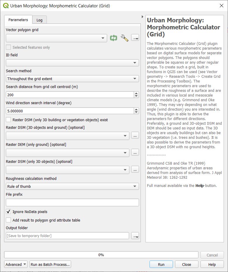
Fig. 3.37 The dialog for the Morphometric Calculator (Grid)
- Search Throughout the Grid Extent
Select if the search should be performed from one side of the grid to the opposite side. Select the other option (Search from Grid Centroid if the search should start from the centroid of the grid. Setting the Search distance can then allow for the search to extent beyond the grid. See the figure below for illustration. The left one performs a search using the grid extent whereas the right illustrates a search from the centroid and extending outside of the grid.
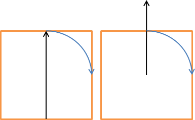
Fig. 3.38 The two search methods for the Search Throughout the Grid Extent option
- Wind Direction Search Interval (degrees)
This decides the interval in search directions for which the morphometric parameters will be calculated.
- Vector Polygon Grid
Here the grid polygon layer should be specified.
- ID Field
Choose an attribute from the selected polygon layer that will be used to separated the different polygon objects from each other. An attribute field of unique numbers or letters should be used.
- Add results to polygon grid
Tick this in if you would like to save a isotropic results in the attribute table for your polygon vector grid.
- Raster DSM (only 3D Objects) Exist
Tick this in if a 3D-object DSM without ground heights is available. 3D objects (e.g. buildings) should be metres above ground.
- Raster DSM (3D Objects and Ground)
A raster DSM (e.g. geoTIFF) consisting of ground and e.g. building height (metres above sea level).
- Raster DEM (only Ground)
A DEM (e.g. geoTIFF) consisting of pixels with ground heights (metres above sea level).
- Raster DSM (only 3D Objects)
A DSM (e.g. geoTIFF) consisting of pixels with object (e.g. buildings or vegetation) heights above ground. Pixels where no objects are present should be set to zero.
- Roughness calculation Method
Options to choose methods for roughness calculations regarding zero-plane displacement height (zd) and roughness length (z0) are available.
- File Prefix
A prefix that will be included in the beginning of the output files.
- Ignore NoData pixels
Tick this in if NoData pixels should be ignored and calculation of grid should be performed eventhough NoData pixels exists within that grid. Nodata pixels are set to the average pixel values of the DEM.
- Output Folder
A specified folder where result will be saved.
- Run
Starts the calculations
- Close
Closes the plugin
- Output
Two different files are saved after a successful run.
Anisotropic result where the morphometric parameters for each wind direction as selected are included.
Isotropic results where all directions are integrated into one value for each parameter.
- Remarks
Units of wai is non dimensional (area building walls / total horizontal area).
All DSMs need to have the same extent and pixel size.
Polygon grids must be squared (or rectangular) and allinged with the CRS used. This will be fixed in future versions so that any shaped grid can be used (see issue #12 in the repository).
- References
Kent CW, CSB Grimmond, J Barlow, D Gatey, S Kotthaus, F Lindberg, CH Halios 2017: Evaluation of urban local-scale aerodynamic parameters: implications for the vertical profile of wind and source areas Boundary Layer Meteorology 164 183–213 doi: [10.1007/s10546-017-0248-z https://link.springer.com/article/10.1007/s10546-017-0248-z]
Kent CW, S Grimmond, D Gatey Aerodynamic roughness parameters in cities: inclusion of vegetation Journal of Wind Engineering & Industrial Aerodynamics http://dx.doi.org/10.1016/j.jweia.2017.07.016
Grimmond CSB and Oke TR (1999) Aerodynamic properties of urban areas derived from analysis of surface form. J Appl Meteorol 38: 1262-1292