Note
Need help? Please let us know in the UMEP Community.
3.22. Urban Morphology: Morphometric Calculator (Point)
- Contributors:
Name
Institution
Fredrik Lindberg
Gothenburg
Christoph Kent
Reading
Brian Offerle
previously Indiana University; FluxSense AB
Sue Grimmond
Reading
Niklas Krave
Gothenburg
- Introduction
The Morphometric Calculator (Point) plugin calculates various morphometric parameters based on digital surface models. These morphometric parameters are used to describe the roughness of a surface and are included in various local and mesoscale climate models (e.g. Grimmond and Oke 1999). They may vary depending on what angle (wind direction) you are interested in. Thus, this plugin is able to derive the parameters for different directions. Preferably, a ground and 3D-object DSM and DEM should be used as input data. The 3D objects are usually buildings but can also be 3D vegetation (i.e. trees and bushes). It is also possible to derive the parameters from a 3D object DSM with no ground heights.
Morphometric parameters
Description
Mean building height (ZH)
Average building height measured from ground level [m].
Standard deviation of building heights (ZHσ).
Standard deviation of building heights [m].
Maximum building height (ZHmax).
Height of the tallest building within the study area [m]
Plan area index (λP)
Area of building surfaces relative to the total ground area.
Frontal area index (λF)
Area of building walls normal to wind direction relative to the total ground area.
Roughness length (Z0)
A parameter of some vertical wind profile equations that model the horizontal mean wind speed near the ground; in the log wind profile, it is equivalent to the height at which the wind speed theoretically becomes zero [m].
Zero-plane displacement height (Zd)
Height above ground where the wind speed is 0 m s-1 as a result of obstacles to the flow such as trees or buildings [m].
- Dialog box
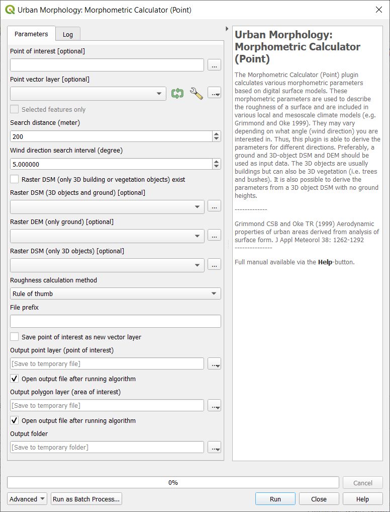
Fig. 3.51 The dialog for the Morphometric Calculator (Point)
- Select Point on Canvas
Click on this button to create a point from where the calculations will take place. When you click button, the plugin will be disabled until you have clicked the map canvas.
- Use Existing Single Point Vector Layer
Select if you want to use a point from a vector layer that already exist and are loaded to the QGIS-project. The Vector point layer dropdown list will be enabled and include all point vector layer available.
- Generate Study Area
This button is connected to the Search distance (m) and when you click the button a circular polygon layer (Study area) is generated. This is the area that will be used to obtain the morphometric parameters.
- Wind Direction Search Interval (Degrees)
This decides the interval in search directions for which the morphometric parameters will be calculated.
- Raster DSM (only Building or Vegetation) Exist
Select if a 3D-object DSM without ground heights is available. 3D objects (e.g. buildings) should be metres above ground.
- Raster DSM (3D Object and Ground)
A raster DSM (e.g. geoTIFF) consisting of ground and e.g. building height (meters above sea level).
- Raster DEM (only Ground)
A DEM (e.g. geoTIFF) consisting of pixels with ground heights (metres above sea level).
- Raster DSM (only 3D Objects)
A DSM (e.g. geoTIFF) consisting of pixels with object (e.g. buildings or vegetation) heights above ground. Pixels where no objects are present should be set to zero.
- Roughness Calculation Method
Options to choose methods for roughness calculations regarding zero displacement height (zd) and roughness length (z0) are available.
- File Prefix
A prefix that will be included in the beginning of the output files.
- Output Folder
A specified folder where result will be saved.
- Run
Starts the calculation
- Close
Closes the plugin.
- Output
Two different files are saved after a successful run.
Anisotropic result where the morphometric parameters for each wind direction as selected are included.
Isotropic results where all directions are integrated into one value for each parameter.
- Remarks
All DSMs need to have the same extent and pixel size.
- References
Kent CW, CSB Grimmond, J Barlow, D Gatey, S Kotthaus, F Lindberg, CH Halios 2017: Evaluation of urban local-scale aerodynamic parameters: implications for the vertical profile of wind and source areas Boundary Layer Meteorology 164 183–213 doi: [10.1007/s10546-017-0248-z https://link.springer.com/article/10.1007/s10546-017-0248-z]
Kent CW, S Grimmond, D Gatey Aerodynamic roughness parameters in cities: inclusion of vegetation Journal of Wind Engineering & Industrial Aerodynamics http://dx.doi.org/10.1016/j.jweia.2017.07.016
Grimmond CSB and Oke TR (1999) Aerodynamic properties of urban areas derived from analysis of surface form. J Appl Meteorol 38: 1262-1292